Feature Configuration
Navigate:  Valuation > Configuration > Feature Configuration
Description
NOTE: Feature Configuration settings are initially setup by your Aumentum Implementation team.
Use this task to define what information is collected for feature maintenance and to map feature-related data fromthe Feature Configuration screen to the RPA main page screen.
Steps
Feature Configuration includes four tabs:
-
Code List – Create and maintain feature-related data.
-
User Defined Fields (UDF) – Create and maintain user-defined feature characteristics.
-
Code Mapping – Map the qualities, conditions and size characteristics available for each feature to create relationships between them.
-
User Defined Fields Mapping – Map user-defined features data together.
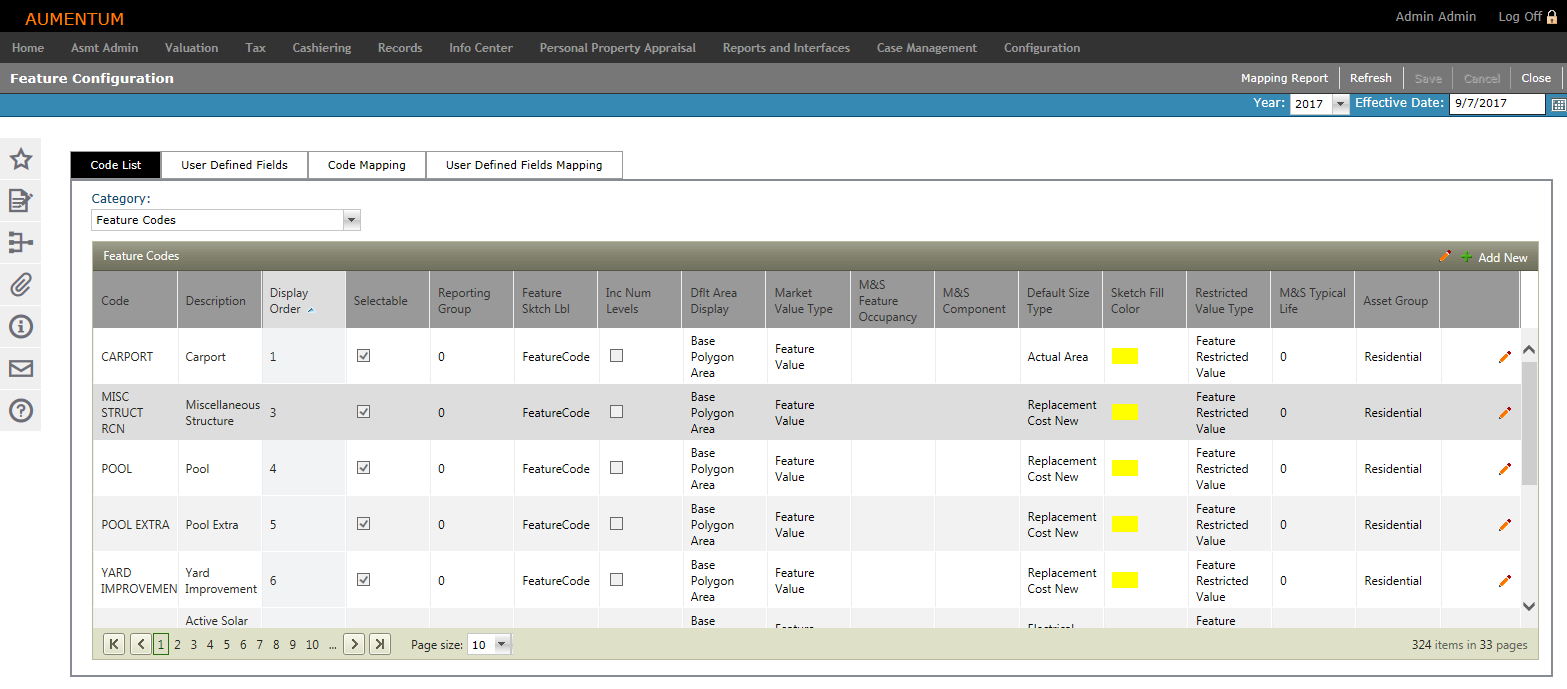
Code List
-
On the Feature Configuration screen, make a selection from the Category drop-down list. The grid populates based on your selection.
-
Click Add New. A new line item is highlighted and active for editing.
-
Define the code's attributes and click the green check mark to save your changes. Click the red X to discard your changes and exit the editor.
-
Some columns display for multiple categories:
-
Code – Enter a brief code.
-
Description – Enter a description of the code.
-
Display Order – Enter a numeric value specifying where the code appears in the list.
-
Selectable – When selected, the code is available for selection in the Aumentum Platform.
-
Reporting Group – Intended to be used in reports if the report designer wants specific items grouped in the same area or summed together
-
Feature Codes
Define general types of features (e.g., detached garage, gazebo, barn, etc.).
-
Feature Sktch Lbl – How the Feature label will be displayed in the sketch.
-
Inc Num Levels – Sketch related.
-
Dflt Area Display – Refers to how the sketch displays the feature (base or gross polygon area).
-
Market Value Type – Value bucket to place Market feature's value.
-
M&S Feature Occupancy– Designate a type of building that can be added and valued as a feature using Marshall & Swift.
-
M&S Component – Link that allows a feature to be valued by MVP (e.g. asphalt, fencing, etc.).
-
Default Size Type – Specifies the size type to display on the Feature sub-tab (RPA main page > Appraisal Site tab), since there may be more than one.
-
Sketch Fill Color – Specify the fill color of the building's sketch.
-
Restricted Value Type – Value bucket to place Use feature's value.
-
M&S Typical Life – M&S related
-
Asset Group – Used to help stratify valuation models. You can select the Asset Group and values in Model Control.
Quality Codes
Defines the building quality (e.g., excellent, average, fair, etc.).
-
Quality Group
-
M&S Quality
Condition Codes
Defines conditions that describe how well a building has been maintained (e.g., excellent, average, fair, etc.).
Structural Element Category
Defines individual structural elements that contribute value to a building (e.g., exterior wall, heating ventilation air, roofing, etc.).
-
ElementType – Category code or unit based.
-
M&S System Code
-
Income Comps
-
Summary View
Structural Element Codes
Defines Structural Element sub-types. Each Structural Element can have many Element Codes associated with it (e.g., living room, kitchen, bedroom, etc.).
-
UnitTypeField – The type of value the Structural Element represents (Capacity, Count, Lineal Feet, Square Feet).
-
M&S Component
-
Rate Group – Used within the Floor Stratified Cost model. Allows a single rate for a group of codes.
Improvement Unit Types
Define different ways features can be measured (e.g., units, square feet, linear feet, cubic feet, etc.).
-
-
Click Save in the Command Item bar.
OR
Click the Pencil icon for an item in the grid. The line item is active for editing.
OR
Click the Pencil icon in the header panel. The entire list is active for editing.
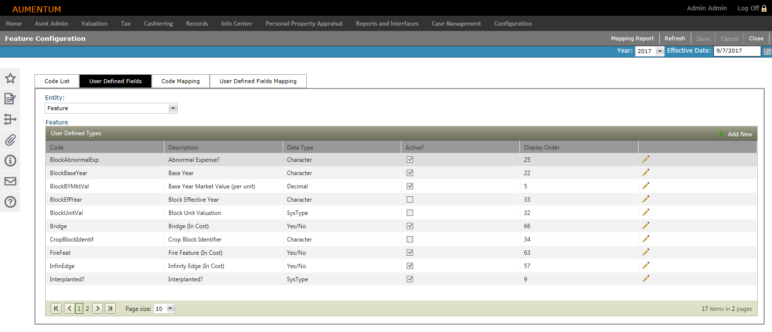
User Defined Fields
-
Select the entity for which you are defining a User-Defined Field (UDF). The grid populates based on your selection.
-
Click Add New in the User Defined Types panel's title bar to add a new code to the selected entity. The grid expands to expose fields for adding the new UDF.
-
Define the new UDF attributes.
-
Code to represent the UDF.
-
Description of the UDF.
-
The Data Type as it should appear on the data entry form.
-
SysType Category is available for selection only if SysType is the selected Data Type.
-
Select whether the UDF is Active.
-
Enter the Display Order as it should appear in the list.
-
Click Insert to add the UDF.
-
Click Cancel to cancel out of task.
-
-
-
Click Save in the Command Item bar.
OR
Click Edit next to an item in the grid. The line item is active for editing.
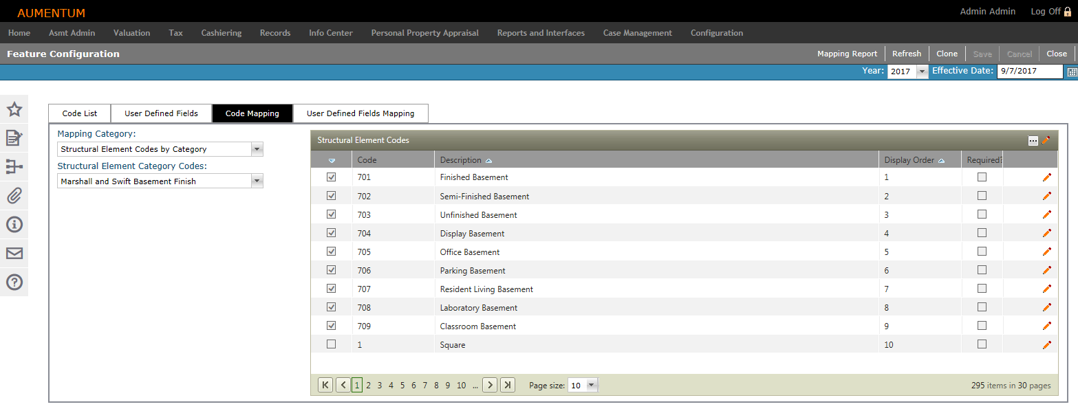
Code Mapping
-
Make a selection from the Mapping Category and Structural Element Category Codes drop-down lists.
-
Mapping Category selection determines the title and content of the second drop-down list (Codes).
-
Codes for the selected categories populate in the grid to the right.
-
-
Click the Pencil icon. The line item is active for editing.
-
Continue editing Code Mappings, as desired.
-
Display Order – Enter a numeric value identifying where the code appears in the select list.
-
Selectable – When selected, the code is available for selection in the Aumentum application.
-
Click the green check mark to save all changes.
-
Click the red X to cancel all changes and exit the editor.
-
-
Click Save in the Command Item bar.
OR
Click the Pencil icon in the header panel. The entire list is active for editing.
OR
Click the Toggle Filter Bar icon in the panel header to display the filtering tools.
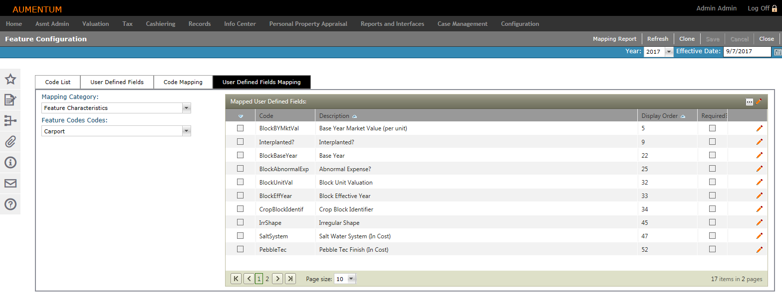
User Defined Fields Mapping
-
Make a selection from the Mapping Category and Feature Codes drop-down lists. Codes for the selected categories populate in the grid to the right.
-
Click the Pencil icon next to an item in the list. The line item is active for editing.
-
Click the Toggle Filter Bar icon in the panel header to display the filtering tools.
Continue editing UDF Mappings, as desired.
-
Display Order – Enter a numeric value identifying where the code appears in the select list.
-
Selectable – When selected, the code is available for selection in the Aumentum Platform.
-
Click the green check mark to save all changes.
-
Click the red X to cancel all changes and exit the editor.
-
-
Click Save in the Command Item bar.
-
Click Refresh to clear all selections and refresh the page.
-
Click Cancel to discard changes since the last Save and retain the current view.
-
Click Close to end the task.
-
OR
Click the Pencil icon in the header panel. The entire list is active for editing.
OR
Cloning
The Clone feature is available in the Code Mapping and User-Defined Fields Mapping tabs. You can quickly clone data relationships from one code to any other code in the same list-level code list.
-
Click the Pencil icon on the row(s) of the item(s) to be cloned, or click the Pencil icon in the header to activate all items.
-
Select the checkbox for one or more items in the Mapped User-Defined Fields panel.
-
Click Clone.
-
In the Appraisal Class Code pop-up, select the checkbox for one or more items and click OK.
-
Click Cancel to cancel the clone task.
-
Mapping Report
Click Mapping Report in the Command Item bar to open the Mapping Report pop-up.
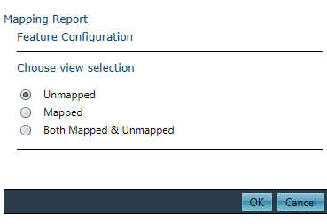
-
Choose a view selection and click OK. The report is automatically exported to a Microsoft Excel worksheet.
Common Actions
Create New Systype – Opens the Select a Systype Category screen to create or edit a systype category.