Building Configuration
Navigate:  Valuation > Configuration > Building Configuration
Description
NOTE: Building Configuration settings are initially setup by your Aumentum Implementation team.
Use this task to define what information is collected for different building improvements and style types, and map related pieces of building improvement data together.
NOTE: Only users with proper permissions can make changes on this screen.
Steps
Building Configuration contains four tabs:
-
Code List – Create and maintain building improvement-related data.
-
User-Defined Fields (UDF) – Create and maintain user-defined building characteristics.
-
Code Mapping – Map related building improvement codes together to define a relationship between them.
-
UDF Mapping – Map related UDFs together to define a relationship between them.
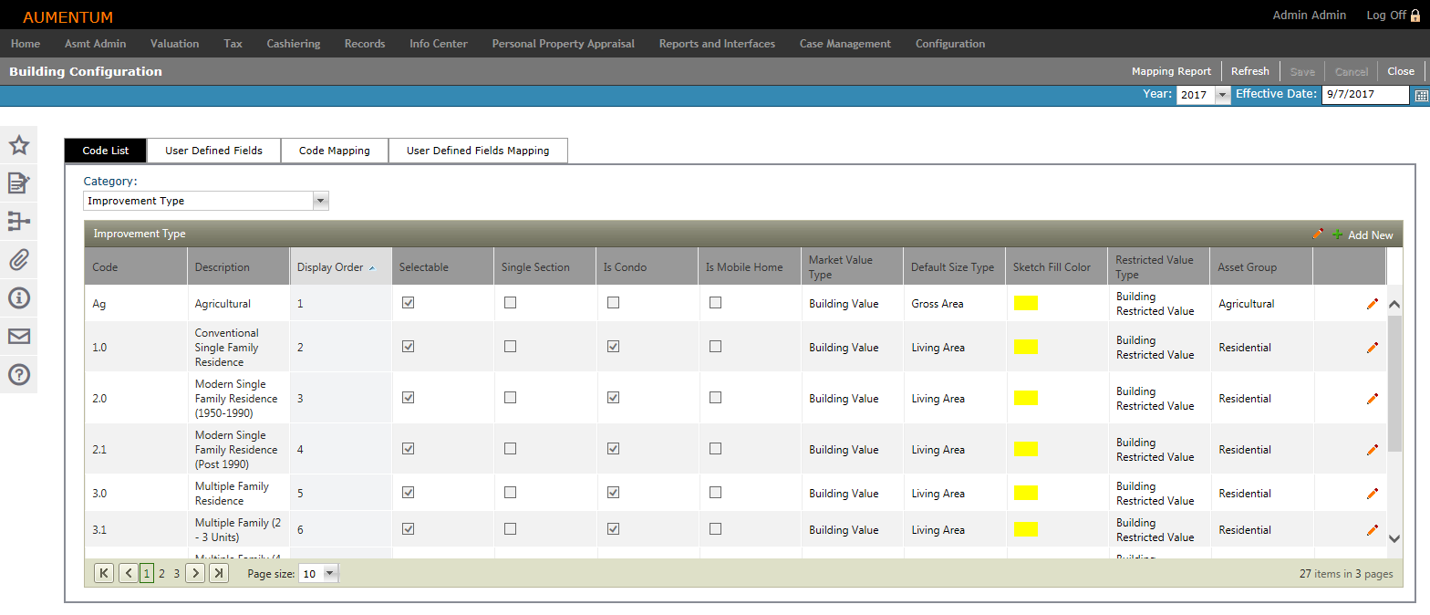
Code List
-
On the Building Configuration screen, make a selection from the Category drop-down list. The grid populates based on your selection.
-
Some columns display for multiple categories:
-
Code – Enter a brief code.
-
Description – Enter a description of the code.
-
Display Order – Enter a numeric value specifying where the code appears in the list.
-
Selectable – When selected, the code is available for selection in the Aumentum Platform.
-
Reporting Group – Intended to be used in reports if the report designer wants specific items grouped in the same area or summed together.
-
-
Single Section – originally planned functionality subsequently dropped but not removed from the UI.
-
Is Condo – originally planned functionality subsequently dropped but not removed from the UI.
-
Is Mobile Home – originally planned functionality subsequently dropped but not removed from the UI.
-
Market Value Type – Value bucket to place Market building value.
-
Default Size Type – The area for the selected size type is displayed in the Building Characteristics grid on the Building tab.
-
Sketch Fill Color – Specify the fill color of the building's sketch.
-
Restricted Value Type – Value bucket to place building's restricted value.
-
Asset Group – Used to help stratify valuation models. You can select the Asset Group and values in Model Control.
-
Default Size Type – The area for the selected size type is displayed in the Section Detail grid on the Building tab.
-
Abv Grade Sktch Lbl – Refers to how the sketch displays the building.
-
Inc Story Height – Refers to how the sketch displays the building.
-
Inc Framing Code – Refers to how the sketch displays the building.
-
Blw Grade Sktch Lbl – Refers to how the sketch displays the building.
-
Show Lvls Blw Grade – Refers to how the sketch displays the building.
-
Dflt Area Display – Refers to how the sketch displays the building (base or gross polygon area).
-
Applies Abv Grade – Determines the use/occupation available for above grade and below grade, namely by filtering the combo box used to select them. Whether a floor is above grade or below grade is based on the FloorType value.
-
If the FloorType is Attic, FullUpper, Number34Upper or PartialUpper then it is treated as above grade.
-
If the FloorType is Basement or SubBasement, then it is treated as below grade.
-
-
Applies Blw Grade – Determines the use/occupation available for above grade and below grade, namely by filtering the combo box used to select them. Whether a floor is above grade or below grade is based on the FloorType value.
-
If the FloorType is Basement or SubBasement, then it is treated as below grade.
-
If the FloorType is Attic, FullUpper, Number34Upper or PartialUpper then it is treated as above grade.
-
-
ElementType – Category code or unit based.
-
Code based – May affect value by % of area (e.g., exterior wall, HVAC).
-
Unit – May affect value by count (e.g., bathrooms, fireplaces).
-
-
UnitTypeField – The type of value the Structural Element represents (Capacity, Count, Lineal Feet, Square Feet).
-
Rate Group – Used within the Floor Stratified Cost model. Allows a single rate for a group of codes.
-
Calculation Options – Determines how size is displayed in the Size field in the Section grid of the Buildings sub-tab (RPA main page > Appraisal Site tab).
-
Summed – Add all similar sections to display a total size.
-
Max – Display the size of the largest of similar sections.
-
Min – Display the size of the smallest of similar sections.
-
-
Unit of Measure – Unit of measure for the associated Size Type (Linear feet, sq ft, acres, etc.).
-
Finished Area – Applies only to Partial Upper factor to size types that are flagged as Finished Area through the Building's Improvement Size Type configuration. For use regarding second floor (or higher) areas with a lower wall at one side, resulting in a lower value for the area.
-
Click Add New. A new line item is highlighted and active for editing.
-
Define the code's attributes and click green check mark to save your changes. Click the red X to cancel your changes and exit the editor.
-
Click Save in the Command Item bar.
Improvement Type
Define general types of buildings (e.g., dwelling, condominium, mobile home, commercial multi-family, etc.).
Improvement Model
Define Improvement Type sub-types that describe the building style (e.g., two story, bi-level, Cape Code, etc.).
Framing Class
Defines the different types of framing used for buildings (e.g., structural steel, reinforced concrete, masonry, etc.).
Quality Codes
Defines the building quality (e.g., excellent, average, fair, etc.).
Condition Codes
Defines conditions that describe how well a building has been maintained (e.g., excellent, average, fair, etc.).
Building Use Codes
Defines how buildings are used (e.g., single family residential, multi-family residential, general retail, etc.).
Floor Key Code
Defines the building's floor types (e.g., ground, basement, first floor, etc.).
Structural Element Category
Defines individual structural elements that contribute value to a building (e.g., exterior wall, heating ventilation air, roofing, etc.).
Structural Element Codes
Defines Structural Element sub-types. Each Structural Element can have many Element Codes associated with it (e.g., living room, kitchen, bedroom, etc.).
Improvement Size Types
Defines different ways buildings can be measured (e.g., a measurement type or type of area that can be measured).
Shape Size Type
Defines building shape types (e.g., square, rectangle, etc.).
OR
Click the Pencil icon next to an item in the grid. The line item is active for editing.
OR
Click the Pencil icon in the header panel. The entire list is active for editing.
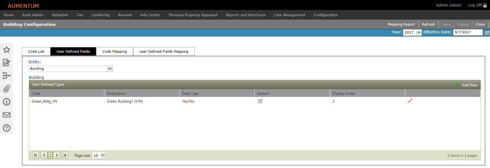
User-Defined Fields
-
Make a selection from the Entity drop-down list.
-
Click Add New in the User Defined Types panel's title bar to add a new code to the selected entity. The grid expands to expose fields for adding the new UDF.
-
Define the new UDF attributes.
-
Code to represent the UDF.
-
Description of the UDF.
-
The Data Type as it should appear on the data entry form.
-
SysType Category is available for selection only if SysType is the selected Data Type.
-
Select whether the UDF is Active.
-
Enter the Display Order as it should appear in the list.
-
-
Click Insert at the bottom of the panel to add the UDF.
-
Click Cancel to discard your changes.
-
-
Click Save in the Command Item bar.
OR
Click the Pencil icon next to an item in the grid. The line item is active for editing.
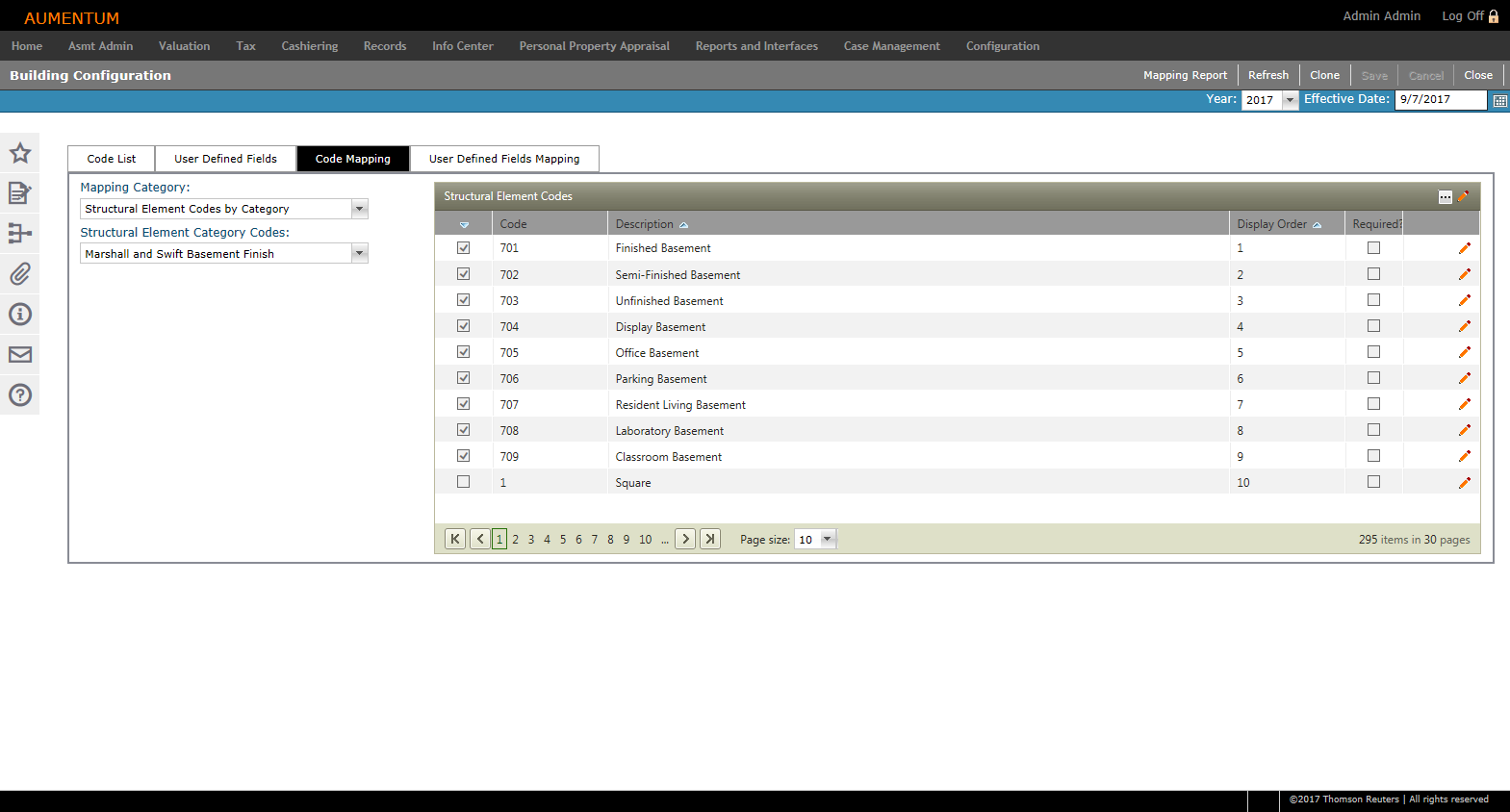
Code Mapping
-
Make a selection from the Mapping Category and Structural Element Category Codes drop-down lists.
-
Mapping Category selection determines the title and content of the second drop-down list (Codes).
-
Codes for the selected categories populate in the grid to the right.
-
-
Click the Pencil icon for an item in the grid. The line item is active for editing.
-
Continue editing Code Mappings, as desired.
-
Display Order – Enter a numeric value identifying where the code appears in the select list.
-
Required – When selected, the code is a required field in the Aumentum application.
-
-
Click the green check mark to save your changes.
-
Click the red X to cancel your changes and exit the editor.
-
-
Click Save in the Command Item bar.
OR
Click the Pencil icon in the header panel. The entire list is active for editing.
OR
Click the Toggle Filter Bar icon in the panel header to display the filtering tools.
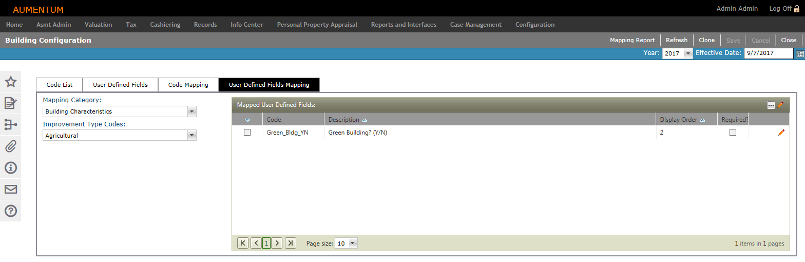
User-Defined Fields Mapping
-
Make a selection from the Mapping Category and Improvement Type Codes drop-down lists.
-
Click the Pencil icon for an item in the grid. The line item is active for editing.
-
Continue editing UDF Mappings, as desired.
-
Display Order – Enter a numeric value identifying where the code appears in the select list.
-
Required – When selected, the code is a required field in the Aumentum application.
-
-
Click the green check mark to save all changes.
-
Click the red X to cancel all changes and exit the editor.
-
-
Click Save.
-
Click Refresh to clear all selections and refresh the page.
-
Click Cancel to discard changes since the last Save and retain the current view.
-
Click Close to end the task.
-
OR
Click the Pencil icon in the header panel. The entire list is active for editing.
OR
Click the Toggle Filter Bar icon in the Mapped User Defined Fields panel header to display the filtering tools.
Cloning
The Clone feature is available in the Code Mapping and User-Defined Fields Mapping tabs. You can quickly clone data relationships from one code to any other code in the same list-level code list.
-
Click the Pencil icon on the row(s) of the item(s) to be cloned, or click the Pencil icon in the header to activate all items.
-
Select the checkbox for one or more items.
-
Click Clone.
-
In the Appraisal Class Code pop-up, select the checkbox for one or more items and click OK.
-
Click Cancel to cancel the clone task.
-
Mapping Report
Click Mapping Report in the Command Item bar to open the Mapping Report pop-up.
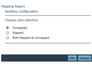
-
Choose a view selection and click OK. The report is automatically exported to a Microsoft Excel worksheet.
Common Actions
Create New Systype – Opens the Select a Systype Category screen to create or edit a systype category.